
THE CONCEPT
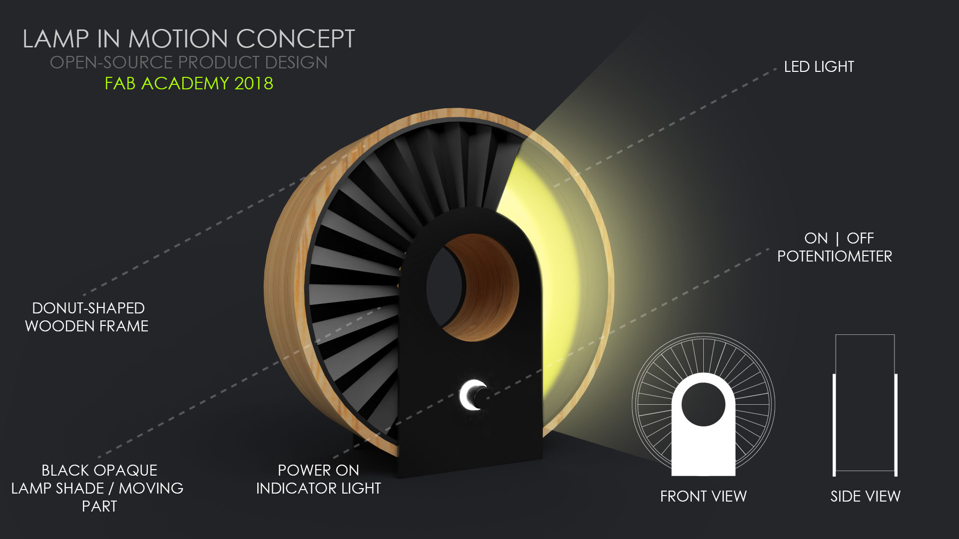
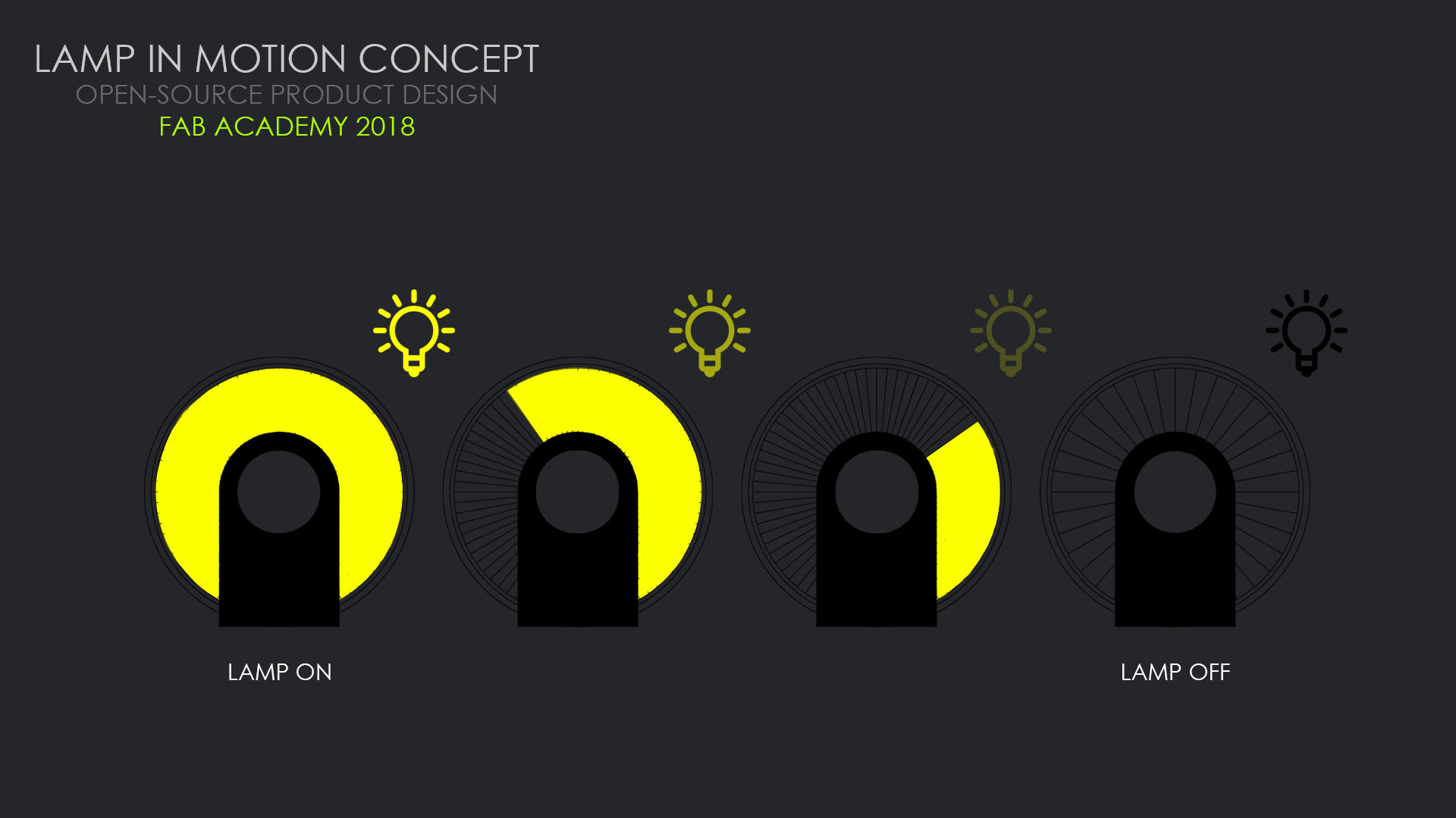
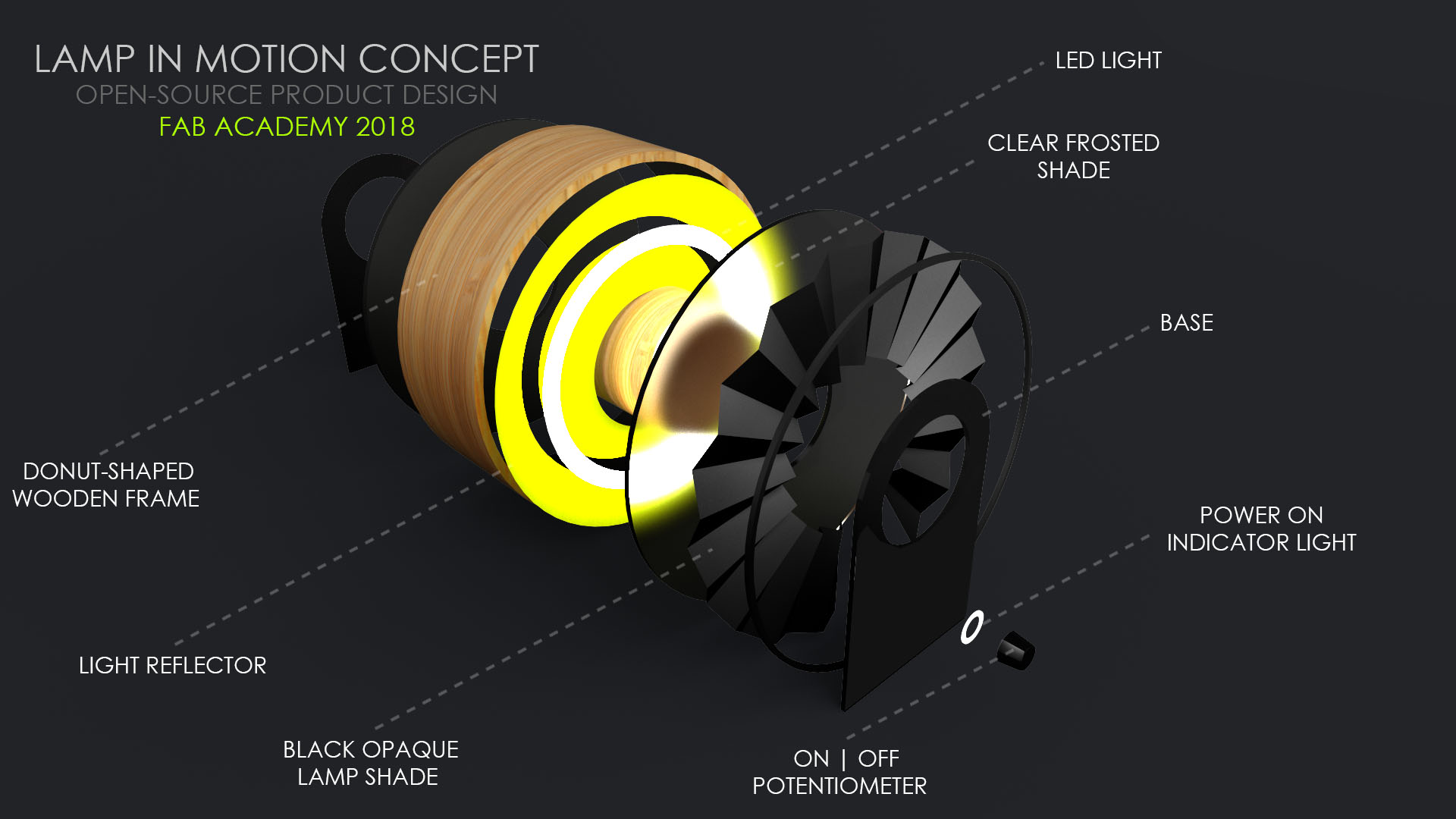
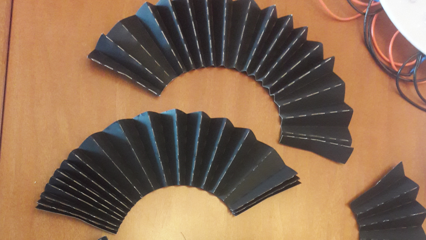
The idea of my final project is to make an interactive indoor smart lamp that has a modern and a dynamic style I want the design to be very minimalist, bold and playful at the same time that is why I chose a simple geometrical form to represent the lamp and I also want to integrate a moving opaque curtain for the light shade in order to change the angle and desity of the light source depending on the user input. the shade of the lamp will be covered by a very thin colored opaque layer that is folded up in the style of origami which can reveal and unveil the light source gradually when turning the lamp on or off and the folding movement will be fully motorized. The lamp will have many features like it can be fully controlled by a smart phone and it can change its lighting colors based on the user pre defined settings for instance the user can choose to switch between warm white and cool white based on the indoor space or outside weather also the user can specify the time to turn the lamp on and off. Finaly,For building the light I'll be using different kind of materials like birch veneer wood for making the outside frame and a frosted transparent acrylic sheet for making the shade and a very thin opaque plastic sheet that can be folded for making the origami curtain in addition to that I'll be using a PLA 3D printer for printing some of the mechanical and fitting parts inside the lamp like the gears and the mounting parts for the geared DC motor the electronic parts.
THE PRODUCTION PROCESS
For making the lamp first I started with doing sketches just to see how the parts will work together and to better understand the mechanism of the moving parts like how the servo will be attached to the folding curtain and how the black opaque curtain will be fixed . Then after finalizing the sketching I started with CAD design for this project I decided to use Rhionceros 3D since I’m familiar with the software and for 2D drafting it has a very fast workflow. For making the form of the lamp I decided to used press fit joints and 2 different thickness of Russian birch plywood 3mm & 6mm, Based on that I drew the structure of the lamp and many other parts listed below in 2D in addition to that I drew the servo holder along with 3 spacers and led holder in 2D in order to 3D print them later on. However, After I was done with drawing all the parts I exported the 2D shapes in DXF file format in order to open them in Inkscape since I was using it for laser cutting . As for the 3D modeled I had created, I exported them in STL format and then I opened them in Cura software in order to prepare the necessary G-code files where I can upload it later on to the 3D printer.
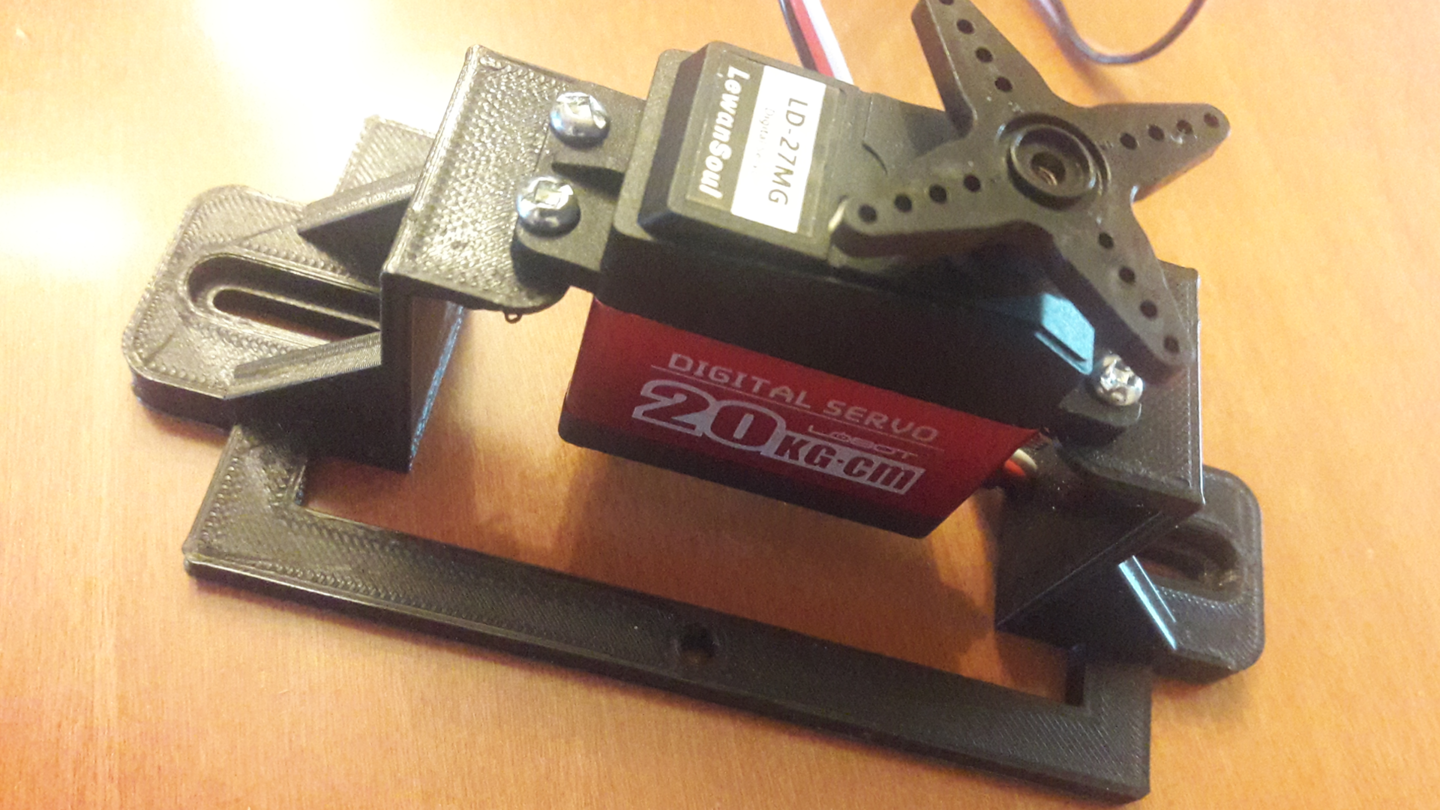
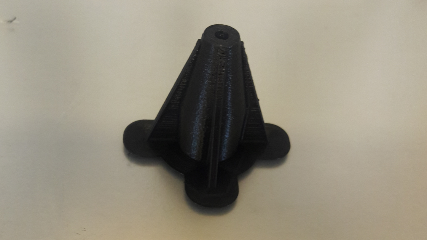
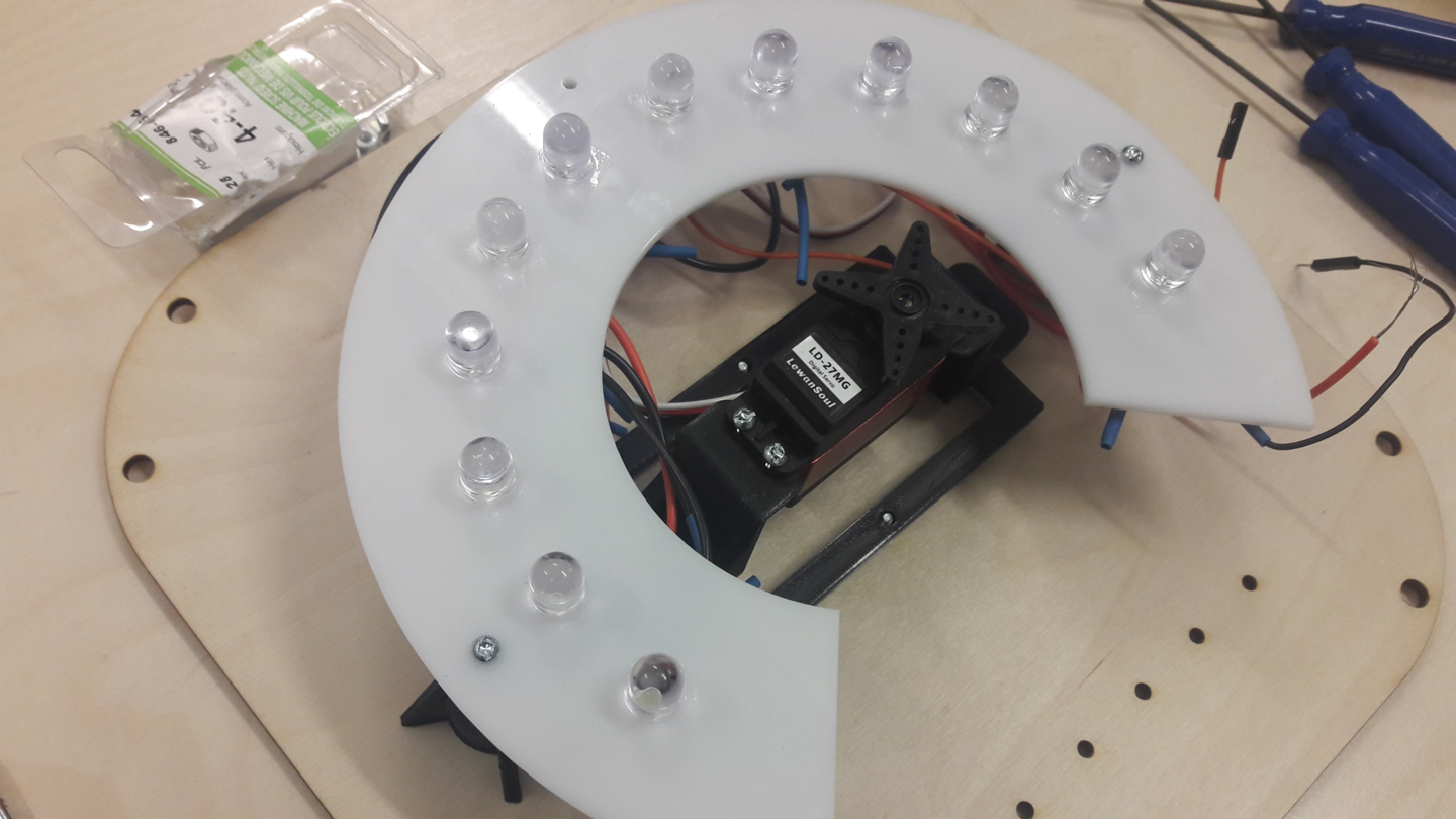
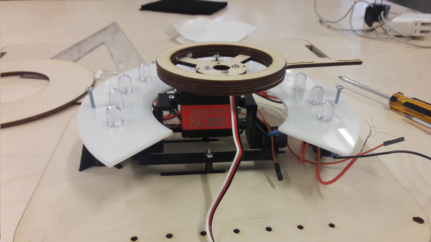
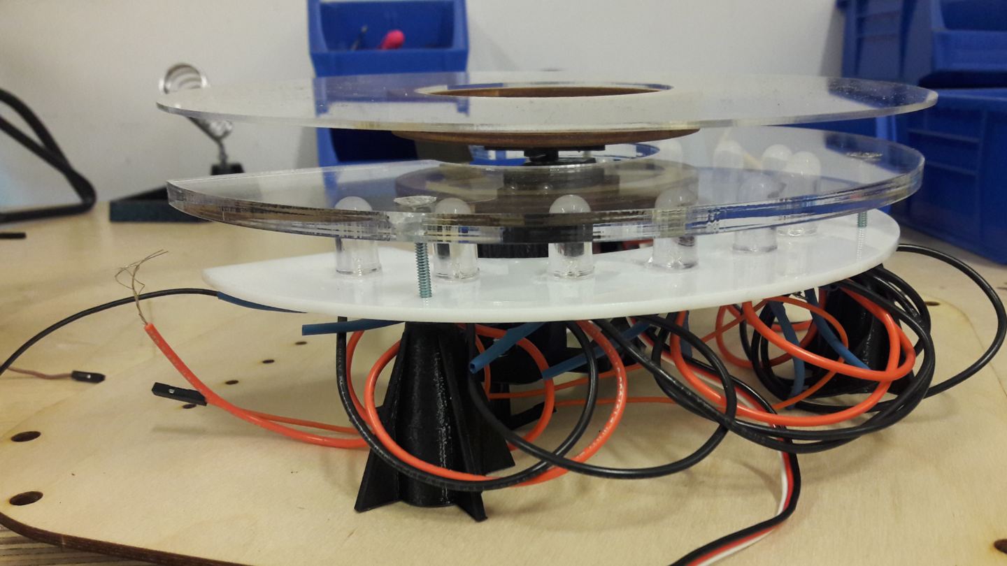
However, For fixing the servo motor on the lamp I printed a 3d servo holder as shown in image #10 in addition to that I printed 3 spacers that were positioned vertically under the white acrylic light holder as shown in image #11
The objects were printed in draft quality and for that I used the same settings that I used in my previous week 3D SCANNING AND PRINTING .
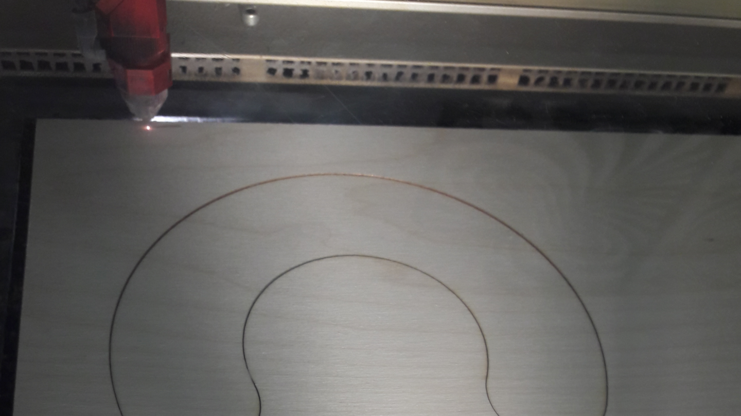
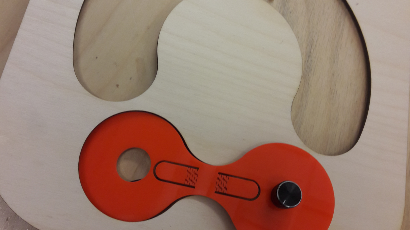
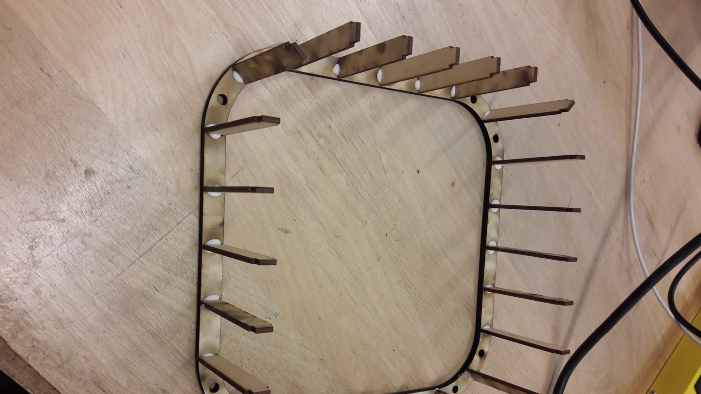
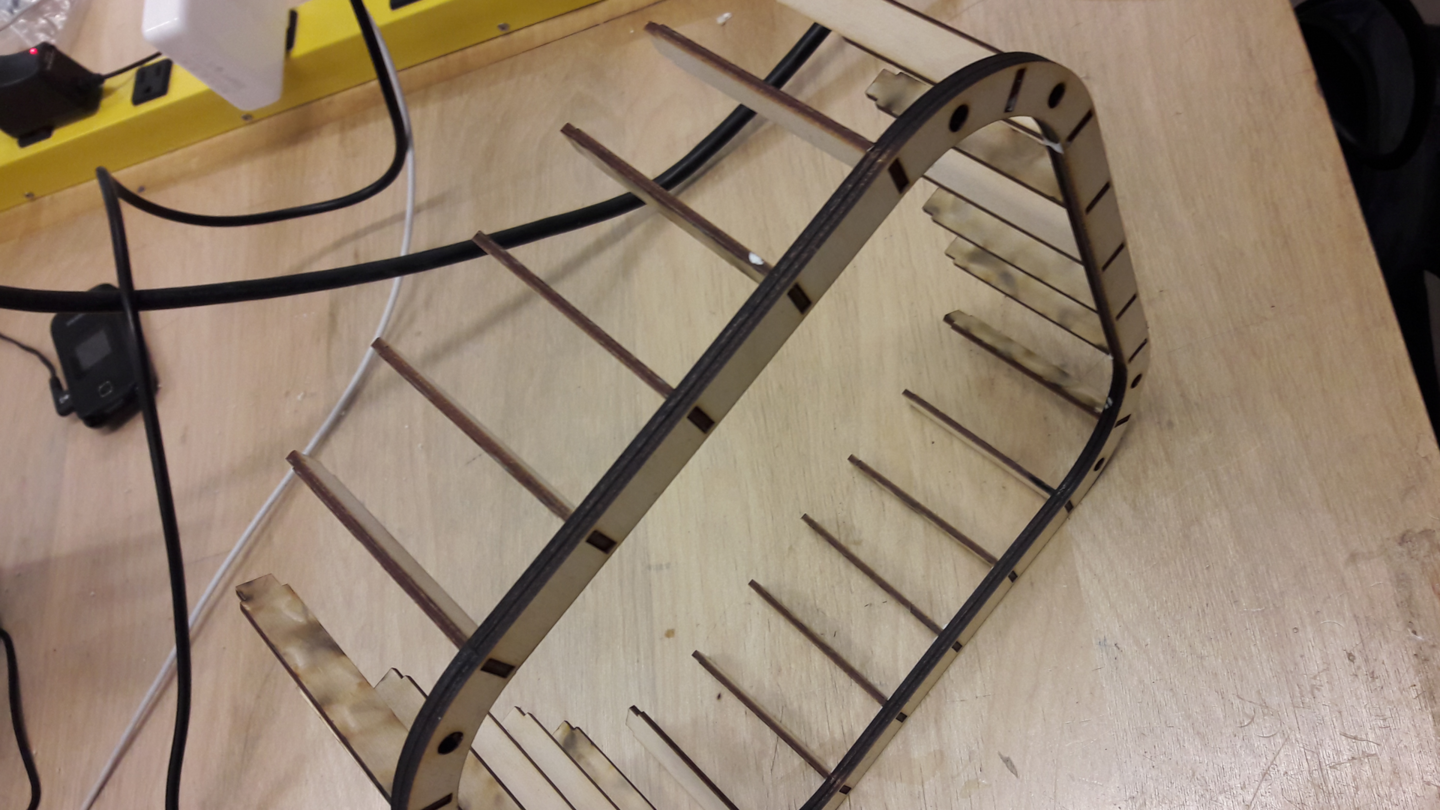
As for cutting the various materials I used the laser cutter I started with cutting the wood frame of the lamp first after that I started with cutting the acrylic sheets and cardboard during the production I was adjusting the setting of the cutter according to the material I was using
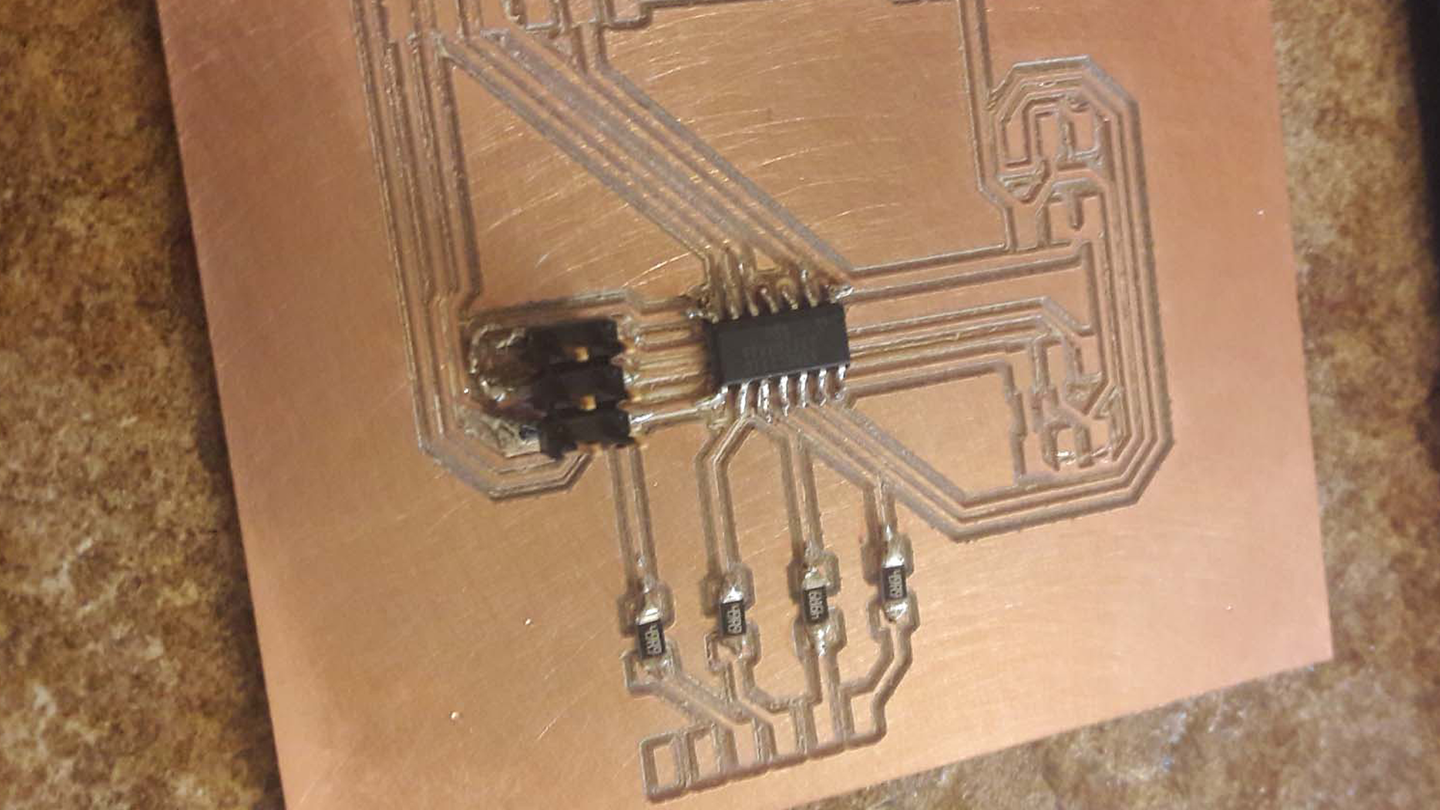
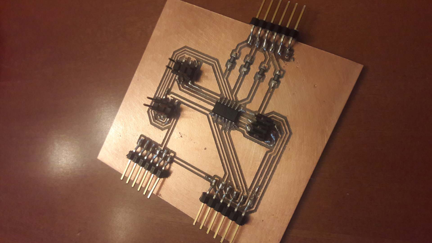
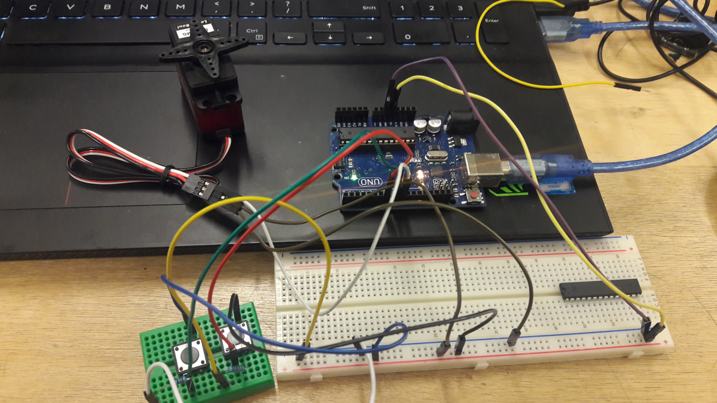
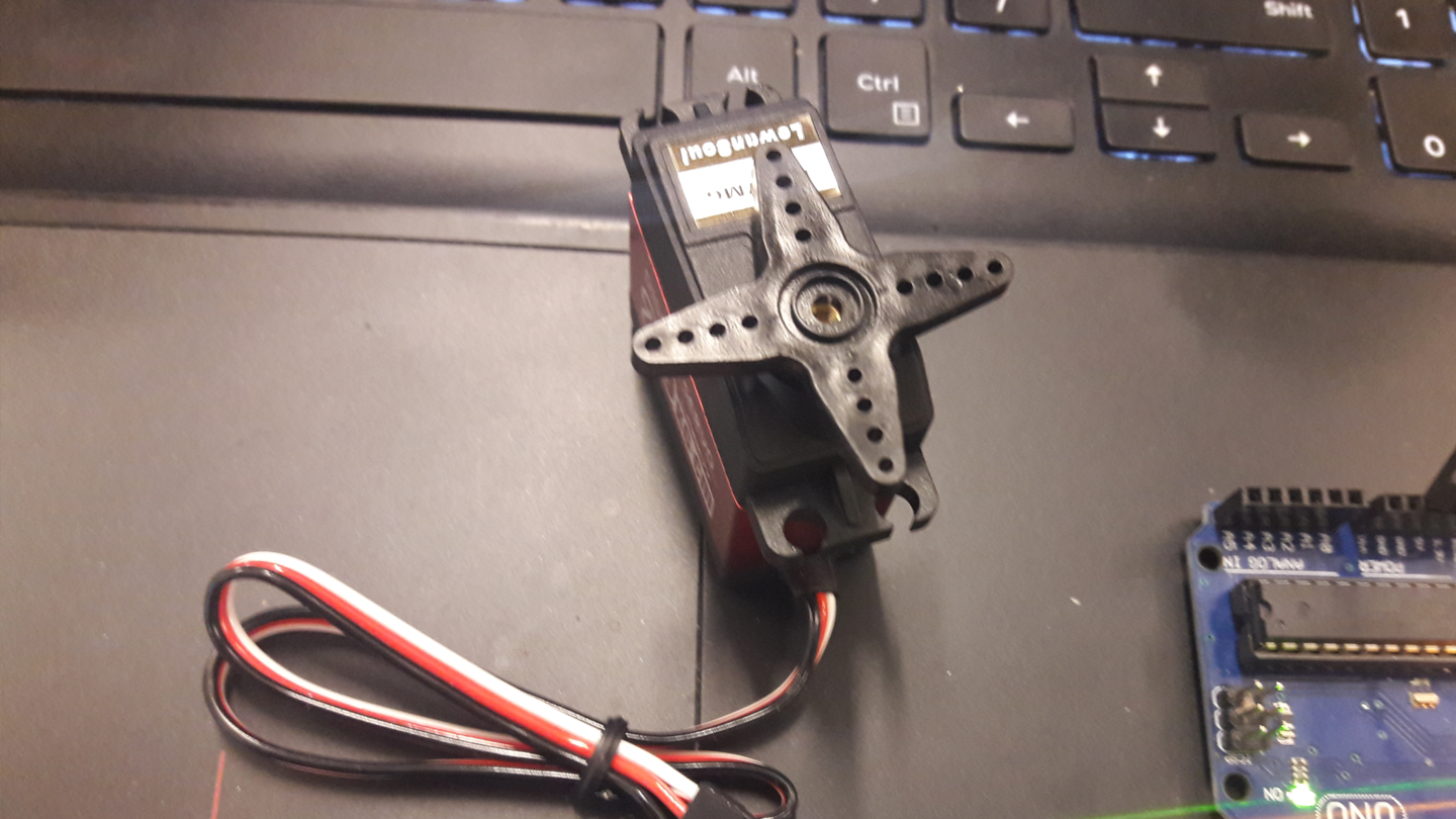
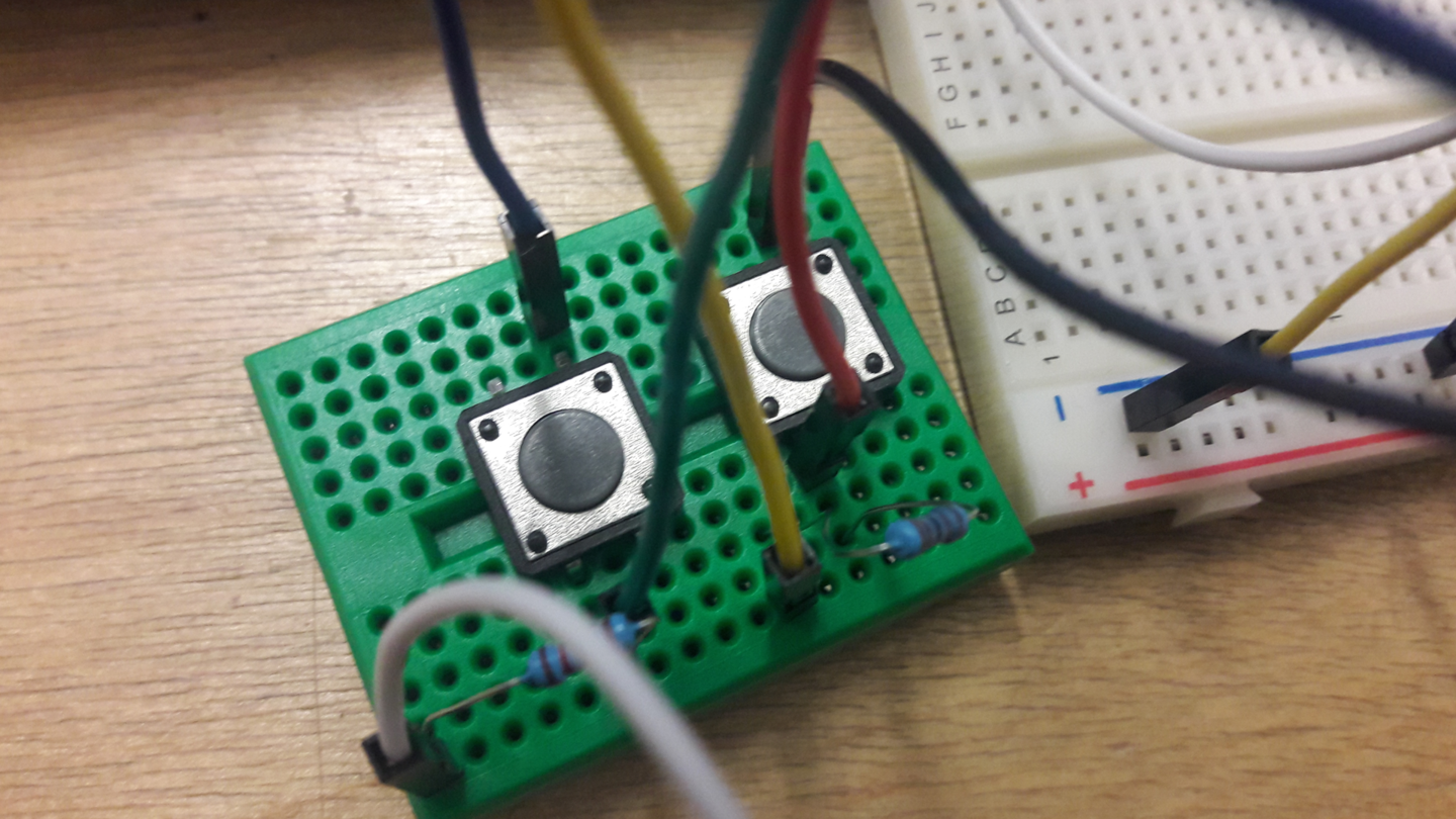
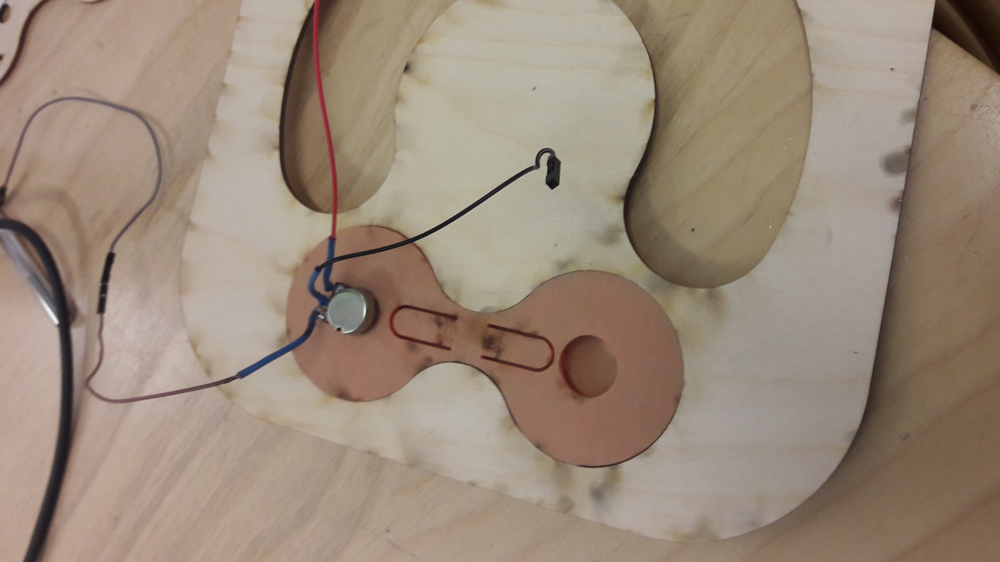
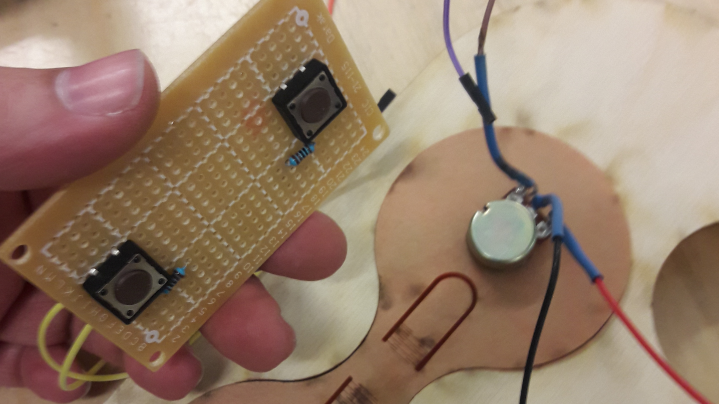
To work on my PCB design first I decided to prototype my idea using breadboard because simply breadboard give flexibility and opportunities to try many ideas quickly and it allows me to run some experiments with circuit designs before moving to designing, milling and soldering my final project PCB The components I used for prototyping my ideas were Attiny44, 1 potentiometer, 2 Push buttons, Breadboards, Jumper wires, Led lights and degree servo, resistors along with Arduino which I used a ISP programmer for programming the Attiny44 chip. My goal was to control the rotation of the servo by 2 push buttons for getting clockwise rotation and anti-clockwise rotation and to control the led lights by a potentiometer and since Attiny has a limited amount of pins and I wanted to use 12 led lights I decided to divide the 12 led I’ll be using into 4 segments where each segment has 3 led controlled by a single Attiny pin. Based on that I dedicated four pins on the attiny 44 microcontroller for controlling the led lights and one pin for the potentiometer along with 3 pins for two push buttons and a servo. Then after I was doing with wiring all the components I used Arduino IDE for writing the code and as mentioned before I used Arduino as an ISP programmer. However, The challenging part with programming the attiny44 chips was making it works with a servo because The default servo library is not supported by ATtiny44, reason being that the servo library relies on a 16 bit timer whereas the ATtiny only has an 8 bit timer. So in order to overcome this problem I used serialservo library inside my code. The code can be downloaded by clicking here However after wiring all the components together I started programming the microcontroller. Controlling the led lights with the potentiometer was pretty easy since this was done in the input devices week This library worked perfectly with the Attiny44 controller initially I ran the default library example tests on my servo just to make sure that everything is working fine and once I saw the servo moving I started writing the full code. Below is the final code I used
/* This code was modified by Georges Hanna, 2018 Fab Academy, final project The code was modified Based on the below codes : + controlling a servo motor by two push buttons http://www.instructables.com/id/Servo-Controlled-by-Pushbuttons/ // + LED Bar Graph https://www.arduino.cc/en/Tutorial/BarGraph */ #include// The compatible servo library with Attiny44 SoftwareServo myservo; // Create servo object to control a servo const int analogPin = 0; // The pin that the potentiometer is attached to analog pin 0 const int ledCount = 4; // The number of the led set I'll connect on my attiny44 int ledPins[] = { 2, 3, 4, 5 }; // An array of pin numbers to which LEDs are attached const int S_buttonPin1 = 6; // Assigning pin 6&7 to the 2 push buttons that control the servo const int S_buttonPin2 = 7; int buttonState1 = 0; // Assigning 0 value to an int variable name buttonState1&2 int buttonState2 = 0; int position = 0; // Assigning 0 value to the servo position void setup() { // loop over the pin array and set them all to output: for (int thisLed = 0; thisLed < ledCount; thisLed++) { pinMode(ledPins[thisLed], OUTPUT); } myservo.attach(1);// Attaching the servo to pin 1 pinMode(S_buttonPin1, INPUT); // Set the 2 pushbottons as input pinMode(S_buttonPin2,INPUT); digitalWrite(1, LOW); // Assign 0 volts to the Servo so I doesn't move if no button is preesed. } void loop() { buttonState1 = digitalRead(S_buttonPin1); // Read the value of Servo button 1 and assign it to buttonState1 buttonState2 = digitalRead(S_buttonPin2); // Read the value of Servo button 2 and assign it to buttonState2 if(buttonState1 ==HIGH && position < 270) /* If buttonState1 is high & the position of the servo smaller than 270 do the following */ { myservo.write(position++); // Incerase the value by 1 while buttonState1 is high (this will rotate the servo clock wise) SoftwareServo::refresh(); // Using refresh to keep the servo updated delay(5); // dalay is used to pause the program for the amount of time } if(buttonState2 == HIGH && position > 0) /* If buttonState2 is high & the position of the servo is larger than 0 then do the following */ { myservo.write(position--); // Derease the rotational value by 1 while buttonState2 is high (this will rotate the servo anti clockwise) SoftwareServo::refresh(); // Using refresh to keep the servo updated delay(5); // dalay is used to pause the program for the amount of time } int sensorReading = analogRead(analogPin); // map the result to a range from 0 to the number of LEDs: int ledLevel = map(sensorReading, 0, 1023, 0, ledCount); // loop over the LED array: for (int thisLed = 0; thisLed < ledCount; thisLed++) { // if the array element's index is less than ledLevel, // turn the pin for this element on: if (thisLed < ledLevel) { digitalWrite(ledPins[thisLed], HIGH); } // turn off all pins higher than the ledLevel: else { digitalWrite(ledPins[thisLed], LOW); } } }
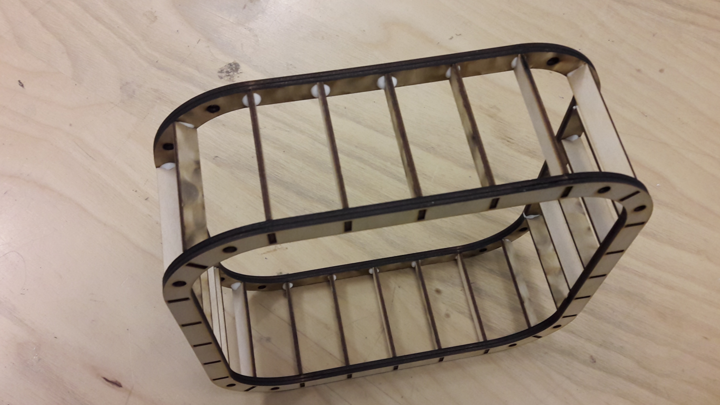
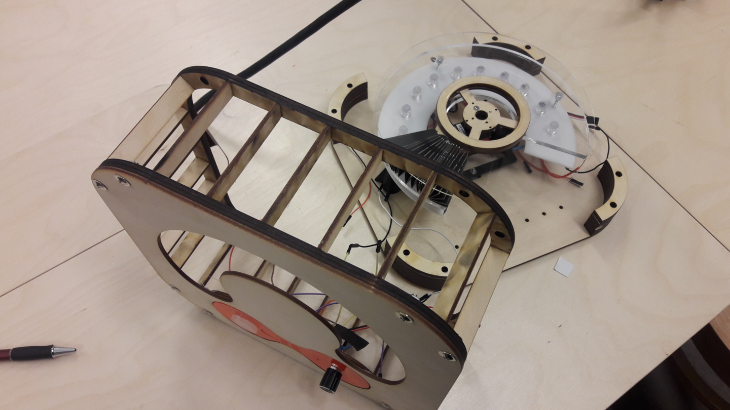
However, After cutting all the parts and pint some of them in 3D I started assembling them according to the design and once I was done with making and assembling the fixed elements I started installing the folding curtain mechanism the challenging part was aligning and centering the rotational axe of the servo with the lamp in order to prevent the arm that is rotating by the servo from hitting the wooden frame structure.
+ WHAT TASKS HAVE BEEN COMPLETED, AND WHAT TASKS REMAIN ?
The following tasks have been completed :
- CAD Design
- Electronic prototyping
- PCB Design & Production
- 3D printing
- Laser cutting
+ WHAT HAS WORKED ?
My final project production process consists mainly of 3 parts electronic design, mechanical design and The PCB I made for my final project is working fine I am able to control the movement of the 270 degree servo by two push buttons in addition to that I’m able to control the led lamps by a potentiometer. In addition to that the mechanism of opening and closing the black opaque curtain is working fine since I’m using a high torque servo
+ WHAT HASN'T ?
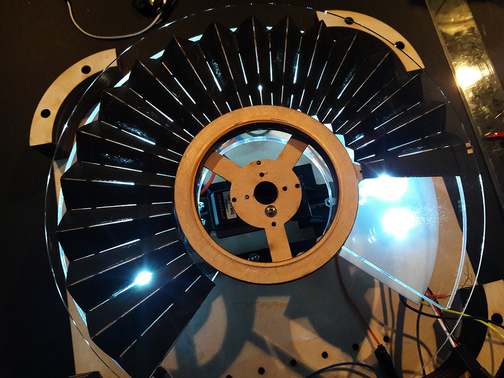
I believe the concept of rotating opaque curtain need more development mechanically speaking it works I’m able control it by the servo but design wise It is not functional as planed due to the low-level led brightness I believe if I increase the quantity of the led lights I can clearly see the effect of the rotating curtain and how the light will be strongly projected on a wall.
+ WHAT QUESTIONS NEED TO BE RESOLVED ?
I have many questions in my head at the moment like what if I want to make this lamp foldable or flat packed ? how can I do that ? if I want to mass produce this lamp which production method is the best ? and why ? What materials I can use in the future in ordered to reduce the weight of the lamp ? What features I can add to the lamp in the future ?
+ WHAT WILL HAPPEN WHEN ?
On my presentation day I manged to present 90 % of the work however the only problem I had that day was not cutting all the laser parts due to a failure in the laser machine.
+ WHAT HAVE YOU LEARNED ?
I learned a lot of awesome things related to electronic design and production in addition to that I had acquired a very good knowledge in avr programing and how I can automate things.